
1. How to interrupt a command from running.
Any command after it’s use required to be interrupted to start using any other tool.
After a tool or command executed please Right click and press Interrupt to stop the command from running.

A shortcut is the  button on the keyboard.
2. Switch to the 3D or plane view.
It is sometimes convenient to see a scaffold from the plane view.
In a 3D view the plane view, as per the grid location on the screen, the Top view as an example.
On an elevation (side) view - the True side view.
Use the Switch to 3D or plane command  located on the Modelling tab to examine the current view from the plane view perspective.
Alternatively, use the shortcut  to switch in between 3D or plane views.
3. View Angle.
To view a model from a different angle Top, Bottom, Left, Right etc. please access the View angle cube located on the contextual toolbar of the view and choose any angle to view the model from.

Note: The combo  (Switch to 3D or plane) will always bring you back to the plane view of the view where the angle has been changed.
Alternatively, rotate the view by Holding down  and Middle mouse button to get any other angle you’d like to see the model from.
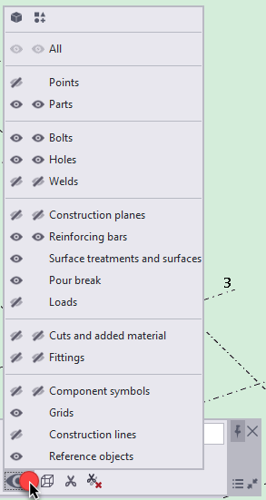
4. Visibility of object types in the model.
Using the view contextual toolbar, it is handy to show/hide construction lines, points, component symbols etc.
Please access the eye and on/off an object(s) type from there.

5. Access to the view properties.
Please double click or right click in the empty space of a view OR right click and and go Properties to get the view properties opened where we can rename the created view, change projection angle, visibility of objects and the view depth.

6. How to hide objects and tools.
Please select an object or tool then Right click and select "Hide" from the context menu. Objects reference lines will be still visible for convenience.
If the same command performed with hold down Shift button (select the object (tool) > Right click > Hold down  > Click Hide). The object or tool reference lines will also be hidden.
Note: The Redraw command available on the Right click in the empty space of the selected view will bring all hidden objects and tools back onto the screen.

7. How to show only selected objects and tools.
The command is commonly used during inspections of an area or modelling around the area required. To eliminate other tools and object from the area selected please select objects and tools required to be shown, Right click and press Show only selected. The only selected objects and tools will be shown rendered – the others almost transparent.
If the same command performed with hold down Shift (select the object (tool) > Right click > Hold down > Show only selected). The object or tool only will be shown.
Note: The Redraw command available on the Right click in the empty space of the selected view will bring all hidden objects and tools back onto the screen.

8. Copy, Move, Rotate and Delete commands.
Tekla commands for copying, moving and rotation as well as deletion of objects and tools are available on the right click while a tool or object selected in the model.
Please watch following videos to learn how to copy, move and rotate tools and objects using Tekla commands.

Tekla commands:
ScaffPlan Commands:
Item tool:
Scaffold Item Tool - Component rotation around axis and end points (couplers)
Scaffold Item Tool - Direct modification of a component
Scaffold Item Tool - Contextual toolbar: Copy commands
Scaffold Item tool - Contextual toolbar: Move and copy using coordinate system manipulator
Scaffold Item Tool - Contextual toolbar: Swap and Mirror commands
Scaffold Item tool - Contextual toolbar: Component rotation commands
Bay tool:
Bay - Copy a bay by a specified number of copies
Bay - Flip, Swap and Mirror bay handles
Tube and clip tool:
9. Change hierarchy of objects in ScaffPlan.
ScaffPlan allows to access and modify any component separately inside of a tool inserted in the model such Wall Trace, Bay tool and others.
Based on the hierarchy levels of a tool as below it is possible to change the hierarchy to 1,2 or 3 from 0 as default and access a component required.
The hierarchy changes when we are holding down  and scrolling the mouse wheel up or down
  .
.
The scroll Up means one hierarchy level down the scroll Down means the level Up.
If clicked in an empty space the hierarchy always gets back to 0 - the default highest level.
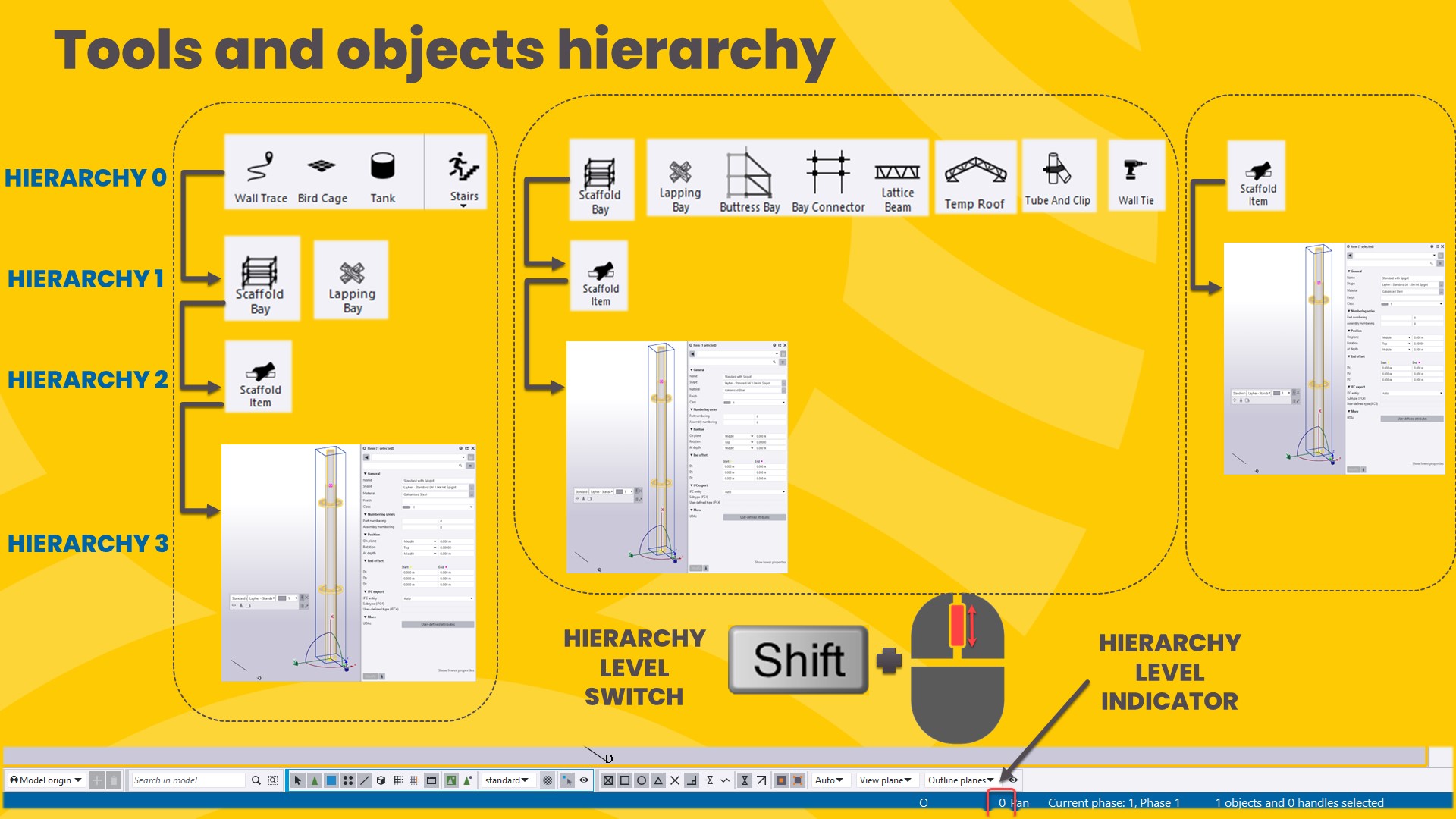
When required hierarchy level set as required an component might be selected in a tool for further modifications.
To get full understanding of hierarchy levels please recap on the following videos below:
Hierarchy of objects in ScaffPlan

10. How to select components start or end points only.
When the only start or end points of components required to be repositioned it is possible to select the only start or end points then perform the move command available on the right click.
To select the start or end points only:
1. Change hierarchy to a level to access a component in a tool (if needed).
2. Select a component(s).
3. Hold down  and window select the only area where the start OR end points located.
4. When perform the Move command. 